PCIe PHY Model in Verilog for PIPE DUT Verification

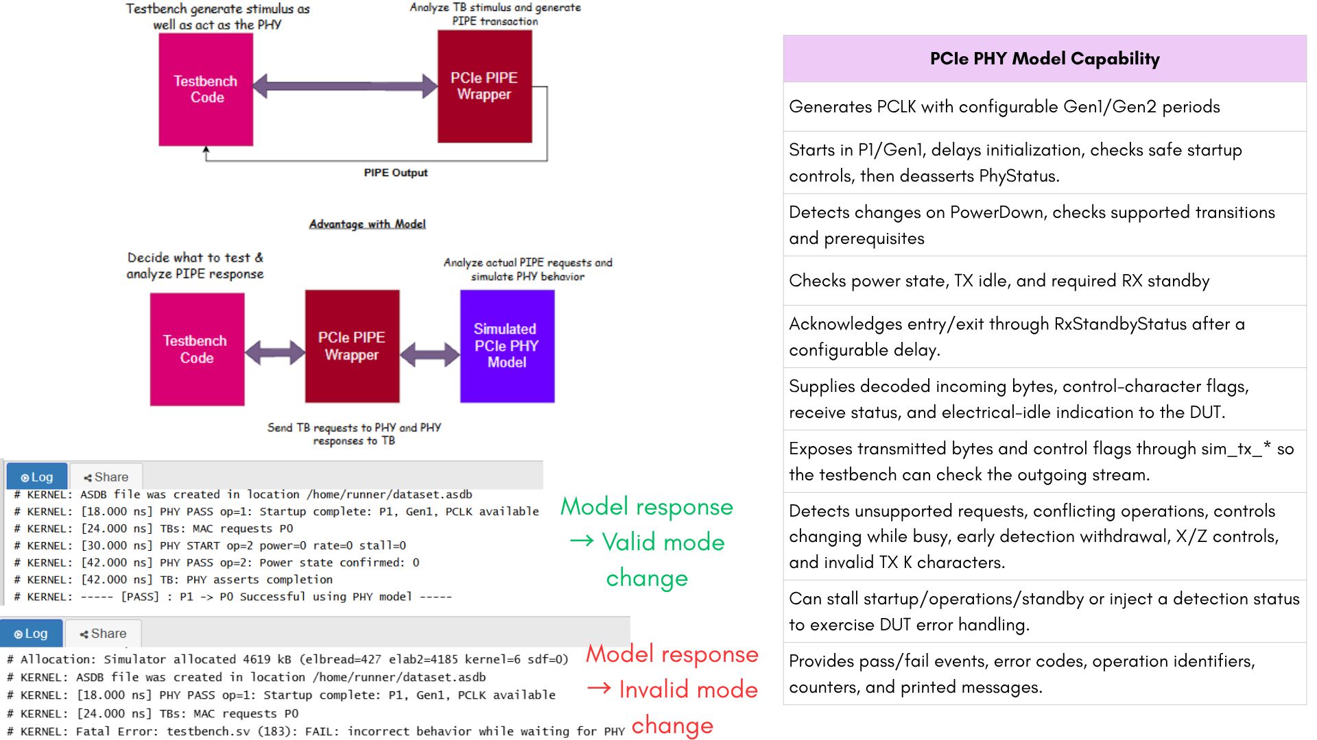
One difficulty we face while testing a PCIe PIPE wrapper is DUT generates PIPE outputs based on the stimulus we apply, but we also need to mimic behavior of PCIe PHY.
Since PHY implementations are vendor-specific, we often generate their responses manually in the testbench. However, generating both the stimulus and the expected PHY responses manually can overlook incorrect DUT behavior.
Therefore, we thought of building model to mimic PHY behavior.
For memory-mapped bus protocols, a memory model can help reproduce read and write behavior. A PHY, however, involves control operations, handshakes, timing, and data transfers. A simple memory model cannot represent all these behaviors.
We build mode that extensively handle control operation. This allows tb to focus on generating MAC transactions for PIPE and analyze PIPE response.
PIPE translates MAC requests into PIPE signals, and the PHY model responds to those signals.
These allow us to focus on the PIPE DUT and testbench while PHY will generate resp.
#1 ] We can control PHY response delays through parameters. e.g., STARTUP_CYCLES controls the initialization delay, POWER_CYCLES controls the power-change delay, and so on. Similarly, we can configure delays for receiver detection and receiver standby. These parameters let us test different response timings and approximate vendor-specific behavior.
#2] The model receives signals from both the testbench and the PIPE DUT, with each serving a different purpose. For receiver detection, the testbench specifies whether a receiver is present at the other end. The model captures this setting when the DUT sends a valid detection request, then returns the corresponding RxStatus after the configured delay. This lets us check how the DUT handles receiver-present and receiver-absent results. The model also supports stalls for startup, power changes, rate changes, receiver detection, and receiver standby, allowing us to test both normal operation and timeout handling.
#3] The model generates PCLK for the DUT, so the testbench does not need a separate clock generator.
#4] The model mimic exact startup and operation-completion signaling used by PHY e.g. startup completes when PhyStatus goes low, while power, rate, and receiver-detection operations complete with a high PhyStatus pulse.
#5] The model checks the rules implemented for its supported PIPE profile before accepting an operation and continues checking relevant controls while the operation is in progress. If a checked rule is violated, such as an unsupported power transition, the model records a diagnostic error, enters a fault state, and withholds successful completion until reset.