Usage of TxDeemph, TxSwing & TxMargin in PCIe

In PCIe Gen1 and Gen2, we often share three parameters from the MAC to the PHY to control the transmitter’s electrical output. These include TxMargin, TxDeemph, and TxSwing. Each performs a unique role.
The PCB channel used to carry signals between two devices behaves like a low-pass filter, attenuating high-frequency components. This is due to the skin effect, which increases conductor loss approximately with the square root of frequency, and dielectric loss, which increases approximately with frequency.
The net effect of both losses is that fast signal transitions are weakened and rounded but slower variations experience less attenuation.
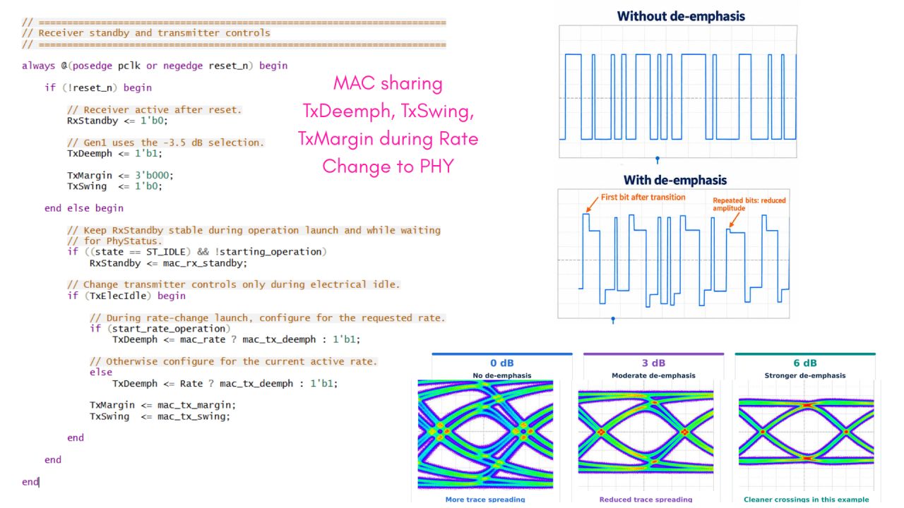
To compensate this unequal attenuation, we make transitions stronger relative to repeated bits. This can be achieved with a tap filter that gives the first bit after a transition a higher amplitude while reducing the amplitude of subsequent bits of the same polarity.
TxDeemph can be either 1 or 0. 1 selects −3.5 dB de-emphasis, so repeated-bit amplitude is approximately 67% of the transition-bit amplitude. 0 selects −6 dB de-emphasis, so repeated-bit amplitude is approximately 50% of the transition-bit amplitude. Gen1 uses −3.5 dB, while Gen2 supports either setting.
Engineers perform channel simulations and hardware measurements to determine whether −6 dB or −3.5 dB gives better eye opening and bit-error performance. The MAC applies the selected setting based on controller configuration and link-training information.
The next parameter, TxSwing, allows us to control the differential voltage swing. When TxSwing is 0, the transmitter operates in full-swing mode, normally with a differential peak-to-peak voltage of 800 mV to 1200 mV. When TxSwing is 1, it selects low-swing operation. The actual normal low-swing voltage range depends on the PHY; 400 mV to 700 mV is explicitly specified for TxMargin setting 001.
Once we have selected the swing and de-emphasis settings, we measure the received signal and check its eye opening. The last parameter, TxMargin, allows us to select different transmit voltage levels during testing, including reduced amplitudes, to evaluate the link’s voltage margin.
This gives us an idea of how much we can reduce the transmit amplitude while still receiving signals reliably at the other end.
TxMargin is usually set to 000 for normal operation. Some nonzero settings have specified voltage ranges, while intermediate levels are vendor-defined. Additional optional settings may not be supported by every PHY.
TxDeemph shapes transition and repeated-bit amplitudes to compensate for the channel’s low-pass behavior. TxSwing selects full-swing or low-swing operation. During margin testing, TxMargin changes the transmit amplitude so we can evaluate eye opening and bit-error performance as the signal becomes weaker.